
Fire Code Compliance Q&A
Welcome to the our Fire Code Compliance Q&A hub, your essential resource for navigating the complexities of fire safety regulations. This comprehensive library of frequently asked questions and expert answers is designed to help building owners, facility managers, and safety professionals stay informed and compliant.
With guidance from Dan Decker, our Industry Affairs Manager, we provide clear, easy-to-understand explanations for the most common fire code topics. From fire alarm system basics to inspection requirements and sprinkler system functionality, we’ve gathered the knowledge you need to make informed decisions and ensure the safety of your property and its occupants.
Click on the questions below to reveal the answers you’re looking for, or contact us directly for a professional consultation.
If after reviewing our fire code Q&A, you feel you’d like to request a service or learn more about how we can assist you, please explore our offerings below:
- Integrated System Design: Learn about how we can combine your fire, security, and access control systems for a streamlined solution.
- Fire Alarm Design & Engineering: For new construction or system upgrades, our team can help with code-compliant design.
- Fire Alarm Monitoring: Ensure your property is protected 24/7 with our reliable monitoring services.
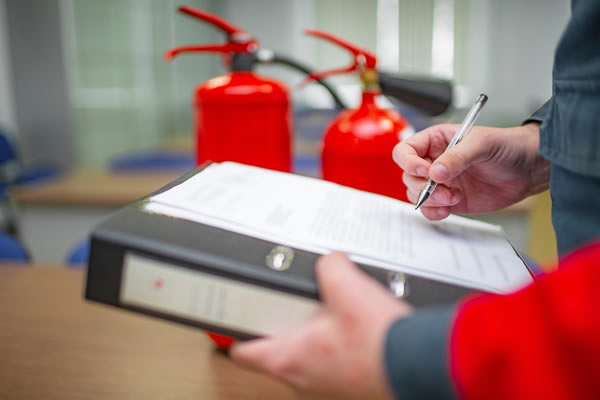
- Fire Inspections: Our certified professionals can perform thorough inspections to keep you compliant with local codes.
Automatic Smoke Detection
Heat detectors can be permitted if ambient conditions (e.g., temperature, humidity, dust) prohibit the proper installation and operation of smoke detectors, and if the early warning provided by a smoke detector is not explicitly required for life safety.
They are typically required when the detector is installed in a concealed location (e.g., above a suspended ceiling) and is not readily visible or accessible for observation. The remote indicator allows for easy identification of the activated detector.
Conditions such as temperatures below 32°F (0°C) or above 100°F (38°C), high humidity, excessive dust, or high air velocity can hinder the proper operation of standard smoke detectors.
Spot-type detectors should be located on the ceiling, or on a sidewall within 12 inches (300 mm) of the ceiling.
For smooth, flat ceilings, spot-type smoke detectors are generally permitted to use a maximum spacing of 30 feet (9.1 m) between detectors, and detectors should be within one-half of the listed spacing from walls. In corridors up to 10 feet wide, detectors can be up to 40 feet between detectors. This still falls under the 30 feet spacing rule, but you need to know the Pythagorean theorem to prove it!
These spaces are generally treated as separate rooms or areas requiring their own detection, especially if they are used as plenums or contain combustible materials.
Detectors should generally be located at least 3 feet (0.9 m) away from the discharge opening of air supply diffusers or return air openings to avoid dilution or interference with smoke entry.
When a building fire alarm system is required, duct smoke detectors (which monitor smoke in HVAC ducts to control fans and dampers) must be connected to the building’s fire alarm control unit. If there is no building fire alarm system, they can annunciate locally.
Duct smoke detectors are required to be listed to UL 268A (Smoke Detectors for Duct Application). Other open-area smoke detectors are listed to UL 268 (Smoke Detectors for Fire Protective Signaling Systems).
For systems with a design capacity greater than 2,000 CFM (cubic feet per minute). This explains why a lot of furnaces are rated at exactly 2,000 CFM.
Yes, exceptions can include if the air distribution systems are incapable of spreading smoke (e.g., serve only one smoke compartment) or for certain exhaust air systems.
If the risers serve two or more stories and have a design capacity greater than 15,000 CFM (cubic feet per minute).
Automatic Sprinkler System Supervision
All valves controlling the water supply for the automatic sprinkler system, including main drain, sectional valves, and any valves that could impair the system’s function, along with water levels in tanks, air pressure in dry/pre-action systems, and air temperature where subject to freezing temperatures
A maximum of 5 waterflow switches are permitted per initiating device circuit.
Waterflow detectors must activate within 90 seconds (1 minute, 30 seconds) of water flow equivalent to the discharge from a single sprinkler of the smallest orifice size for which the system is designed.
A maximum of 20 supervisory switches are permitted per initiating device circuit.
They should activate when the valve is turned off or otherwise moved from its normal open position (typically within two turns of the hand wheel or when the valve is 20 percent closed from its full open position).
They should activate when the pressure deviates by +/- 10 psi (69 kPa) from the normal operating pressure.
Water pressure tanks must be supervised for high and low water level (e.g., within 3 inches of the required level). Other tanks, such as gravity tanks, are typically supervised for low water level (e.g., when the level drops 12 inches below the required level).
Supervision must be provided for the temperature of water in tanks and other water storage facilities exposed to freezing temperatures, typically signaling when the water temperature drops below 40°F (4°C).
Exceptions can include jockey pump control valves, control valves to small, specific hazards like cooking hoods or paint booths where the valve is locked open, or certain trim valves to pressure switches in dry, preaction, or deluge systems that are sealed or locked open. Underground key or hub gate valves in roadway boxes are exempt.
Suppression system alarm and supervisory devices and circuits should be designed and installed to initiate a signal if they are tampered with. This includes trouble signals if junction box covers or device covers installed outside buildings are removed. Tamper-resistant screws can sometimes be used as an alternative to tamper-supervising covers.
Fire Pump Supervision
Common indications include: Pump or Motor Running, Loss of Phase (for electric pumps), Phase Reversal (for electric pumps), Controller Connected to Alternate Source (for electric pumps), Controller Off or Manual (for engine-driven pumps), Low Oil Pressure (for engine-driven pumps), High Engine Temperature (for engine-driven pumps), Low Fuel Level (for engine-driven pumps), Controller Trouble, and Engine Trouble.
These critical valves are commonly supervised by an approved supervising station (e.g., central station, proprietary, or remote station service), a local alarm that causes an alarm at a constantly attended location, locking the valves in the open position, or sealing the valves with weekly inspections and placement within fenced enclosures.
Fire pump test outlet valves are typically required to be supervised in the closed position.
Where the pump room is not constantly attended, audible or visible signals, powered by a source other than the engine starting batteries and not exceeding 125 volts, must generally be provided at a point of constant attendance.
A fire pump “Pump Running” signal is permitted to be classified as either a supervisory signal or an alarm signal. However, all other fire pump signals (e.g., trouble, power failure, low fuel) are typically required to be supervisory signals. Because fire pumps are generally programmed to automatically run weekly or monthly tests, it is a good idea to program the “Pump Running” signal as a supervisory signal, and avoid weekly alarm activations.
Remote indication (to a fire alarm control panel or supervising station) ensures that personnel at a constantly attended location are immediately aware of the fire pump’s operational status, power supply issues, or any trouble conditions, allowing for prompt investigation and response to maintain fire protection readiness.
NFPA 25 generally requires weekly no-flow (churn) tests for diesel engine-driven fire pumps and certain electric pumps (e.g., those taking suction under lift), and monthly no-flow (churn) tests for other electric pumps. Additionally, a comprehensive annual flow test is required for all fire pumps to ensure they can deliver their rated capacity.
Common alternatives include physically locking the valves in the open position, or sealing the valves in the open position combined with documented weekly inspections. These methods help ensure the valves remain in the proper state for the fire protection system to operate.
These signals must be powered by a reliable source other than the engine starting batteries and typically should not exceed 125 volts. This ensures the signals function independently of the pump’s primary power and starting system.
Fire pump supervisory signals are typically required to be transmitted to an approved supervising station, which can include Central Station Service, Proprietary Supervising Station Alarm Systems, or Remote Supervising Station Alarm Systems, depending on the occupancy and local code requirements.
Manual Fire Alarm Systems
Generally, yes, a minimum of one manual fire alarm box is required. The principle is that even with automatic detection, the sprinkler service technician or the building owner should have a means to manually initiate an alarm, especially when connected to a supervising station (NFPA 72, 23.8.5.1.2).
Exceptions typically include:
- Fire alarm systems dedicated solely to elevator recall control (NFPA 72, 23.8.5.1.3).
- Certain occupancies (e.g., some fully sprinklered Group R-2 apartment buildings) where local authorities having jurisdiction (AHJs) have granted specific exceptions based on a comprehensive fire safety strategy.
They must be securely mounted and on a background of contrasting color. The operable part of the initiating device should be between 42 inches (1.07 m) and 48 inches (1.22 m) above the finished floor.
They must be mounted within 5 feet (1.5 m) of each exit doorway on each floor. Additional boxes are typically located so that the travel distance to the nearest box does not exceed 200 feet (61 m). For grouped doors over 40 feet (12 m) in width, they should be mounted on both sides and within 5 feet (1.5 m) of each side of the grouped opening.
Manual fire alarm boxes are universally required to be red in color to ensure easy identification.
Protective covers are often installed to prevent physical damage or malicious false alarms. These covers are typically clear or red with a transparent front and should not emit a local alarm unless specifically approved by the Authority Having Jurisdiction (AHJ).
Manual fire alarm boxes must always be accessible, unobstructed, unobscured, and clearly visible at all times to ensure they can be used effectively in an emergency.
Yes, manual pull stations are permitted to be either single-action (requiring only one step to activate) or double-action (requiring two steps, such as lifting a cover then pulling a handle).
Normally, yes. However, when testing a sprinkler supervisory system it is recommended to leave the single required pull station on active monitoring, while the balance of the system is on test. This pull station also needs to be tested to verify it reports to the supervising station.
NFPA 72 states that the values presented for measurements are expressed with a degree of precision appropriate for practical application and enforcement. It is not intended that the application or enforcement of these values be more precise than the precision expressed in the code (NFPA 72, 1.6.5). For example, if a measurement is given in inches, it typically implies a tolerance of plus or minus 1/2 inch.